
Fields to Calculate Areas in AutoCAD – Part 2
It’s a cold Saturday morning in Michigan. As I am sitting here drinking my coffee I wanted to respond to a question on a post I wrote about using fields in AutoCAD. It was one of those moments where I thought…..hmmm yeah you can do that with AutoCAD fields.
Part 1 below is my original post about using fields to calculate an area and add to a label. A direct question came to me about saying “Sam, it would be nice if you could have a field to add up areas of several objects.” The answer is yes, you can with a table or a mathematical formula right in the field. Move to part 2 for the explanation and a video explaining both processes. I am going to focus on the portion without the table then show you a quick demonstration on how to add the areas in a table.
Figure 1: Total Area in a field (left image) and total area in a table (right image).

Part 1
I am sure we have all had to calculate an area of a pond, footprint, or some other irregular shape in AutoCAD. What about those times when we need to convert to acres, simple – right? We just get out our calculator or use the onscreen calculator and do the math. Let’s let AutoCAD do that for us. We are now going to locate or create a closed object or polyline in a drawing and place a leader with mtext on an object and use a field to label the area (in acres) of the object. Let’s first drawing an irregular shape on our drawing. Next type the mleader command and place a leader pointing to the object as shown in Figure 2.
Figure 2: Object – Mtext – Label

Notice how we do not have anything after the “=” sign for the area. Right click and highlight (red box) where you want the number to be in your mtext and select insert field as shown in Figure 3.
Figure 3: Right click-Insert Field

You now need to change the field category to Objects (1) and then hit the Object type button (2) and you will be sent back to out to the AutoCAD screen to select the object.
Figure 4: Select the Object

Select the outer bold line (boundary) in your drawing. The field selection window will pop up. Select Area then Decimal. But wait, we want acres and this is in standard units 1-1 which would be square feet. We are assuming that the coordinate system is setup to decimal units or 1-1. Therefore the value displayed in the field will be in square feet and not acres. We just need to additional format to the field. Checking the coordinate system is very important for any type of calculation. Make sure you are in the correct coordinate system and your drawing units are correct.
Figure 5: Field selections
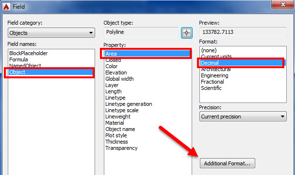
Select the additional format button as shown above in Figure 5 above and another dialog box will pop up and you can add some custom formatting. We need to convert the value to Acres and we also would like to add a suffix as shown in Figure 5 .
- Step 1 you are going to divide the value by 43,560 which is how many square feet are in an acre.
- Step 2 you will add a Suffix, in this case we are adding the word ACRES.
Figure 6: Additional Format

You now have linked a field with additional format to an object in AutoCAD. If you revise the boundary the field will automatically update with the new area shown in Acres. If you break the link between the object and the field, simply right click and reselect the object following the steps above. Your final output should look just like Figure 6 below. Don’t forget to change the precision to your desired output, you can change this in the additional format window as shown in Figure 6.
Figure 7: Area Calculation Shown

Part 2
We have our areas again just like in Part 1. Except in this example we have 3 separate areas that we would like to calculate the square footage individually and also add it to a field which will update if any one of the 3 areas updates. Simply follow the steps in part one selecting each object (in this case the polyline) and adding some additional format as shown in Figures 1 and 2 below.
Figure 1: Object – Polyline – Preview

At this time we do not want to add any additional format until we get to the last field added.
Step 1: Select the object or outline of the pond. It must be a closed polyline-then make sure the object type is area as shown.
Step 2: Change the units to decimal with the precision of 0.0.
Step 3: Drag your mouse and copy the field selection
Step 4: Go to the formula and paste in the number and add a + after it.
Figure 2: Adding all 3 formulas to one Field in a Formula


After completing the first one then go back to the object tab and get the area for the second object. Your final Formula section should look like what is shown below.
Once you get all 3 in there go to the additional format section again and add your custom prefix and suffix as shown.
Figure 3: Add those areas including additional format


You now have a field based off 3 objects that will add up if the geometry of those objects change. The following video will go through all the steps on how to have these areas calculated automatically.
This year I am speaking at Midwest University and my class is Getting Productive with Plan and Production in Civil 3D. This is such a cool topic and I am looking forward to presenting. At Haley & Aldrich we have had some projects over the past year that included very long alignments and roads. The plan and production tools worked great and we were able to streamline the process of setting up our sheets.

That’s all for now, you all have a great rest of your weekend wherever in the World you may be.
Until next month……Sam