
I hope this post finds everyone safe and healthy. Autodesk University 2021 was digital again last year and I was able to present Professional Tips and Techniques on Sheet Sets in AutoCAD. With over 700 people on the question and answer session I found it fun and exciting, and yes I went very fast. Many questions were answered by the people on the call in the chat window along with myself and my moderator David Cohn (Thanks David!). One of my goals this year will be to provide updated screencasts providing you all of the answers to the use and functionality of Sheet Sets. Yes, including using within BIM360 as there were several questions surrounding that topic. We do not know what 2022 will bring at this time but it would be great to see everyone in person and present a class consolidating all of the material and notes I have gathered while teaching sheet sets at Autodesk University.
System variables are always a topic of discussion. For this tip I want to talk about the CURSORSIZE system variable in AutoCAD. For many years I have been using an Autolisp routine to switch the cursor size from 3 to 100, flipping back and forth. I find this helpful when working on design projects especially in tight areas where there is a lot of geometry. The ability to flip back and forth to get a better view can be helpful. For this I created a simple lisp routine named cx.lsp. To use the code copy and paste into notepad and save to a name cx.lsp (or your preferred name).
;;; Lisp Routine to toggle cursor size between 100 and 3.
;;; Simple lisp routine to flip the cursor size quickly in AutoCAD
;;;
(defun c:cx ()
(if ( = 100 (getvar “CURSORSIZE”))
(if (not PREV_CURSORSIZE)
(setvar “CURSORSIZE” 3) ; then
(setvar “CURSORSIZE” PREV_CURSORSIZE) ;else
) ;end if
;;;
This same concept can also be applied by creating a macro and placing it on a tool palette as shown below. The first macro will set the cursor size to 100 and the one below will change back to a 3. The images below show how this simple macro can change that system variable quickly and one additional image using diesel code to create a cursor toggle. Copy and paste the code into your button properties on the tool palette.

Macros to change the cursor from 100 to 3
- ^C^C_CURSORSIZE;100
- ^C^C_CURSORSIZE;3
Macro to toggle cursor size using Diesel:
3. ^C^C$M=$(if,$(=,$(getvar,cursorsize),100),cursorsize;3;;,cursorsize;100;;)
At Autodesk University in the past I presented a lab and lecture on macros in AutoCAD. Many macros and exercises are provided with the handout and you can find a link to the classes here:
Mighty Macros: Powerful commands to pump up productivity.
Pumping up Productivity in the LAB with Macros, One Character at a Time
In some of my future posts I am going to start shifting over to Map 3D and Civil 3D. Although I love writing about AutoCAD, I primarily use Civil 3D in my workflow and have some fun topics to share in the future
Stay healthy and safe wherever in the World you may be – until next month – Sam


Annotation text objects in AutoCAD are used in drawings to determine text height or the overall scale of an annotation text object. An annotative object whether it be text or a block is set to a scale in model space at a particular paper height then when the viewport scale is changed the object changes its scale based off that factor.
If the annotative property of an annotation object is enabled, the text height or scale of the annotation object adjusts based on the current drawing annotation or layout viewport scale with the result that it will remain at the same size automatically.
Annotative Objects continue to be key learning component for many AutoCAD users. For Civil 3D users all our labels and styles are annotative which means the concept becomes more of a natural workflow.
There are two commands (one system variable) that I find helpful when working with Annotative objects. The first is the system variable SELECTIONANNODISPLAY. This variable will control the “faded visibility” or multiple scales showing up when you select the text or object as shown below.

The default value is set at 1, change the system variable to 0 and your multiple annotative scales will not appear.

Many times we want to see those different object scales giving us the visual display to help determine if the location is correct at an alternate scale. If you want the text and/or leader to be pointing at the same spot in all places then you must reset the annotative object. This can be controlled by Synchronizing Multiple-scale options as shown below.
- Select your object (text shown below)
- From the menu select Annotative Object Scale
- Select Synchronize Multiple-scale Positions.
This will reset the location of all the annotative scales to align with the current scale selected.

This year at Autodesk University 2021 I taught Professional Tips and Techniques using the Sheet Set Manager in AutoCAD. Extremely faced paced and a very fun class. If you get a chance check out the video here and download the materials from this session and my previous two sessions on Sheet Sets.
If the community keeps up the interest I will propose to present all of the tips and tricks I have learned over the past 6 years of teaching Sheet Sets at AU. There are some changes coming and by the time we meet again next year we can dive into those and discover the most productive workflow needed to make our daily lives easier.
Have a great weekend wherever in the World you may be.
Stay healthy and safe – Sam
We are not in Vegas but we are virtual this year and it has been great! Here is my class and a quick CAD tip on converting text imported from a pdf file.
Autodesk University 2021 for the Americas kicked off this week and I am presenting and moderating tomorrow! I am excited and honored to present again on Sheet Sets in AutoCAD.
This is the third installment of a 3 part series which includes over 50 tips on how to become more efficient using the sheet set manager. We are going to dish out as many tips as we can in the hour timeframe. Please put the questions in the chat and I will do my best to answer all of those over the next week or so. It’s going to be fun so join me tomorrow!
We will go fast but you will gain the knowledge you need to succeed and all the resources to help you along the way. I will be throwing out tips in the chat as we go, get ready to take notes, copy, paste, and have some fun with Sheet Sets.
Professional Tips and Techniques using the Sheet Set Manager in AutoCAD

Now for a quick CAD Tip. This post will show you how to convert SHX font geometry to text after importing a PDF file in AutoCAD. You ensure good text recognition by specifying the SHX font name used. Unlike other fonts, SHX fonts import as lines, arcs, circles, and other geometry instead of text.
PDF files are the most common file format used when exchanging design information between designers, contractors, clients, and others. AutoCAD 2017 introduced the ability to import PDF files. The PDFIMPORT command imports PDF data into AutoCAD as 2D geometry, TrueType text, and images.
Let’s first import the data. On the insert tab of the Ribbon select the PDF Import button.

Notes: Adobe’s PDF file format doesn’t recognize AutoCAD SHX fonts. When a PDF file is created from an AutoCAD drawing, text that was defined with SHX fonts is stored in the PDF as geometry. When you import the file you get lines and arcs that define the text object. With AutoCAD 2020 you have a new text recognition tool that enables you to select imported PDF geometry representing SHX text and convert it to text objects. You can find this on the import tab of the Ribbon as shown.
After selecting the file you will see the Import PDF dialog box where you will have several options on how you want the file to be imported.

- PDF data to import: Options to select how your data will import.
- Do you want layers?
- Preview of the imported file.
- Import options – several options for blocks, hatches, and lineweights.
- Alternate options for importing the file
- Select OK.
Once you drawing is imported follow the workflow on the ribbon. Here is where you can recognize the SHX Text, Change Settings and Combine Text.

Here is a quick Video showing you how to import a PDF file into AutoCAD and then Recognize the SHX text changing those lines to editable text objects.
That’s all my friends – enjoy the rest your week, stay safe, and check out my class recordings from Autodesk University 2021.
Have a great rest of the week wherever in the World you may be!
Until next month, Sam
Last year I wrote an article in AUGIWorld on Using Layers for Collaboration. This post will highlight some of the features of that article.
Layers are a fundamental feature of AutoCAD, used to apply colors, linetypes, lineweights, transparency, as well as control plotting characteristics. Not using layers efficiently or placing everything on layer 0 will only cause rework and headaches for the next person working on your drawing. It is critical to understand layers and use all the tools within AutoCAD to your full advantage.
Let’s start by examining how AutoCAD sorts layers. On the Home tab of the ribbon you will find the layer panel located within the center of the ribbon tab as shown in the image below. Open a drawing, select Layer Properties, and examine how the layers are sorted within the file.

The name of the layer can be the first step in controlling layers. By default, layers are sorted by name. If you give layers logical names, it becomes easier as drawings become more complicated. From the image below you can see the layers are sorted alphabetically starting with an “A” as the main descriptor. I added B and C to show how the layer sorts. You can select the name column to reverse the order as shown below.

The AutoCAD out-of-the-box template file does not include any layers, so you need to establish this standard on your own. Have you ever looked at the layers provided within a Civil 3D® drawing file? The image below shows the layers that are provided within the Civil 3D Template.

The layers created in the Civil 3D templates follow the National CAD Standards Rules (NCS). The layers follow the National CAD Standards standards as follows, with each element separated by a dash.
Discipline Designation: Required; the AutoCAD Civil 3D templates use the C and V discipline designators, which stand for Civil and Survey/Mapping. The discipline designator is one letter.
Major Group: Required; identifies elements such as roads, topographic elements, and storm sewers. To adhere to the standards, custom Major Group fields are not allowed.
Minor Group: Optional; identifies sub-elements such as road profiles. You can include up to two minor groups per layer name, and you can define your own custom Minor Groups. For example, the layer C-ANNO-TABL-TEXT has two Minor Groups: “TABL” and “TEXT,” both consisting of four letters.
Minor Group: Additional layer classes.
Status: There can also be a one letter status indicator on the end.

Managing Your Layers with Filters
There are two kinds of layer filters in AutoCAD. These filters allow you to create named sets of layer selections involving many different disciplines. The two buttons shown above the filter section will navigate you to the correct filter as shown below.

To create a group filter, select the New Group Filter button in the filters list as shown and the filter will be added. Follow the steps below to create your group filter.
- Rename the filter to a logical name.
- Highlight all the layers you want to be in that group (they do not have to have the same properties or a common name).
- Drag the layers to the filter.

A more detailed way to stay organized is with a properties filter. Upon selecting this button, you have more flexibility based on the layer names you choose. In this example we are going to give a simple criterion—including all the layers with a prefix of A and then we are going to add all the layers with a prefix of V. Keep in mind you can use wildcards (*) after the character to include all the layers with those features as shown below.

After you add the letters with the wildcard, select OK and you can now view the layers in your properties filter as shown.

Select the links below to find helpful tips on using layers in AutoCAD.
Resetting a layer in AutoCAD with a Macro
Renaming a Group of Layers with Wildcards
Using the Layer Translator in AutoCAD
Change with width of the layer combo control bar
Finally, Autodesk University 2021 is going digital and it is FREE! Please register and take time to connect and learn from your peers. For those of you who have been unable to attend this is your chance to get a look and feel for how the event is organized and how people teach and present. It is going to be fun!
Have a great weekend wherever in the World you may be. Stay healthy and safe.
Sam
Within this post we are going to review 3 separate commands located on the Express tools tab of the Ribbon in AutoCAD. The AutoCAD Express tools are a collection of tools that help support and enhance the productivity of AutoCAD. You can access the Express Tools from the express tools tab on the ribbon and you can also type the corresponding command at the command prompt.
- Align Space – This command will take a model space view and align your viewport in paper space to match.
- Synchronize Viewports: This command helps line up those viewports perfectly where you can add a match line for a better representation.
- Merge Layout – This command will take unused layouts and merge into one consolidating your design drawings.

The next 3 videos will review each of these parts of the Layout tab on the Express Tools panel.
Autodesk University will be digital again this year which gives you the opportunity to attend and collaborate with your peers. I have decided to submit proposals for 3 classes this year.
CLASS ID: CES500047: AutoCAD System Variables Explained!
System variables in AutoCAD are values that control command settings, interface behavior, and user options. AutoCAD has well over 900 system variables working in the background while you use the software. Some system variables are stored within the drawing file while others are stored in the Windows registry. In this class you will learn how to redefine important system variables to maximize your efficiency using AutoCAD. We will review and alter many system variables and understand how they can affect the behavior of AutoCAD. After gaining an understanding we will discover how to implement the System Variable Monitor and System Variable Editor to help us manage and maintain a standard approach to your design workflow.
Class ID: CI50002: Making your Move from AutoCAD to Civil 3D
You have been presented with the task of moving from using AutoCAD to Civil 3D on a design project and soon realize that the two programs are very different. Civil 3D is a complex civil design tool which is part of the Autodesk AEC collection. This course is designed to give you a basic introduction on how to make a successful move from AutoCAD to Civil 3D. We will review how to make the move from general AutoCAD design and drafting into a more BIM approach using Civil 3D. We will start with a comprehensive review of the Toolspace palette. We will import point files, create surfaces, alignments, and profiles. A review of the differences between data shortcuts and external references will be covered and we will close with a general overview of some of the more complex design features of the software. We will cover the basic topics of the software and provide you a general overview of all the features included in Civil 3D to help you get started on your design journey.
Class ID: CES500018: Professional Tips and Techniques Using the Sheet Set Manager
Following up from A Complete Guide to the Sheet Set Manager this class will focus on professional tips and techniques while using the Sheet Set Manager. We will do a deep dive into the commands and settings and all components of the Sheet Set Manager covering over 50 tips that will help you increase your productivity. We will start with creating multiple templates for different disciplines, then review the Sheet Set Palette and how you can leverage that on projects, and finally covering areas that you may or may not be familiar with when using the Sheet Set Manager. This class will help you understand the power behind the tools included in the Sheet Set Manager that are rarely used or ignored. At the end of this class you will be able to apply your knowledge to take your designs to the next level by connecting the data and staying on top of current industry practices.
Enjoy the rest of your weekend wherever in the World you may be. Stay healthy and safe – until next month.
Sam
Do you every get annoyed by those default layout tabs in AutoCAD? Why are they there? Can I remove them? I always instruct my users to rename the layout tabs (right-click-rename) to an appropriate name and/or remove if they are not used. Here is a trick on how to remove those tabs using a macro placed on a tool palette.
The default setting in AutoCAD will display a Model Space Tab along with a Layout1 (1) and Layout2 (2) tabs as shown in the image below. The Model tab represents model space which is where you draft and design the model of your project. The Layout tab represents the paper space environment where you create layouts typically including title blocks, general notes, and a window of items drawn in model space.

First of all, you cannot delete the Model Tab; that is default by AutoCAD and used to create your model or geometry. The Layout tabs are paper space tabs added by default to assist you as you begin your project. When adding a new drawing or a template (3) you may see the following appear with Layout1 and Layout2 still visible. We want to delete those but do it quickly. You can select the image for additional information on switching between the Model Space and Layout tabs.

To delete a layout tab manually you right click the layout and select delete. That’s a lot of picks and clicks. Notice all of the options included when you right-click. You can rename, create a new layout, insert a new layout from a template (HINT: does not have to be a .dwt file). Select the image below to be taken to a knowledge based article on importing layouts from a template. I like clean drawings and require my users to delete these tabs, rename, and cleanup while on a design project.

Let’s create a macro to remove those tabs and cleanup your drawings. The easiest way for us to create and use a macro is on a tool palette. Open up any tool palette right click in the palette area and hit New Palette as shown. This will bring up a new blank palette in AutoCAD.

Next, we need to get a command in there. There are a few ways to do this but in my experience type CUI at the command prompt and type the word “delete” (Step 1). I want to look for a command which I can also use the icon (or edit) so it represents something similar to what I am trying to accomplish. Left click and drag the command (Step 2) onto the tool palette as shown. At this point we are just getting the command in there with the images.

After the command has been added to the palette, right click the icon and select properties. We are now going to complete 5 steps as shown below. Actually only 4 since we already have our image in there.
- Drag the command from the CUI onto the tool palette.
- Rename the name of the command for the user to understand the objective.
- Give a brief description of what the command does. PLEASE give a description, it helps for the next guy or gal that goes in there and launches your new command.
- The most important step. We need to change the MACRO. We will review in detail below.
- The image. If you did not import an image from the CUI or another button you can right-click and specify your own image. Keep in mind there is a dark and light theme in AutoCAD which means you need to check the appearance of the image for both. I know, one extra step now but I do like the dark theme.

In AutoCAD macros can be shortcuts to a series of commands to help make the process of design more efficient. In Figure 1 a macro is stated as a single instruction. Use the action recorder to record a series of commands and build a macro then run it automatically to repeat a series of steps. To write a macro, you type the commands in the macro properties section as you’d type them in at the command line. If a command displays a dialog box, you would place a dash in front of the command to suppress the dialog box. We will cover special characters as we begin to build our macro. Let’s examine our Delete Layout Macro.
^C^C^R_layout;d;layout1;_layout;d;layout2;
^C^C Cancels the current command in AutoCAD – Do it twice!
^R Turns command versioning on or off. We need this when working with Layouts.
_Layout Issues the layout command.
; The semi-colon represents a return on the keyboard. You can also enter a space here but I recommend the semi-colon which you can clearly identity the action.
d Delete the layout.
_Layout1 Deletes Layout1
The macro then continues to delete another layout named layout2. If you only have layout1 in your drawing it will be deleted and no other action will be taken.
Until next time…..Have a great weekend….Sam
What do I mean by a creating a blank space or a non-breaking space using a field in AutoCAD? Entering data using fields in AutoCAD is an extremely efficient way to connect the data and keep consistent throughout your design project, especially when using Sheet Set Manager. In my class at Autodesk University 2020 we explored A Complete Guide to the Sheet Set Manager. This class was a hands-on-lab with 15 exercises and one of those was entering Sheet custom data into our Sheet Set Template.
In word processing and digital typesetting, a non-breaking space, also called no-break space, non-breakable space, hard space, or fixed space, is a space character that prevents an automatic line break at its position. Within the SSM you can insert a non-breaking space which will give you the ability to have a cleaner output by inserting a blank field.
We are going to review exercise 4 from my Sheet Set Class and a video of the non-breaking space. Keep in mind some virtual computers do not allow you to enter the non-breaking space but we were able to use %% or %%U to capture the same effect. You can perform this same function with your standard company title block to provide consistency on your design projects.
Start AutoCAD and open up a Sheet Set that already contains a sheet within the set.

If you are following along from the Autodesk University class, open up the Sheet Set in the Exercise 4 folder

Right click on the Sheet Set Project, then select properties from the fly out menu.
Select Edit Custom Properties on the lower left of the dialog box.
![]()
For this task we will add sheet custom properties. We are going to edit sheet custom properties by adding 01-Drawn by and 02-Checked by. Why the 01 and 02? AutoCAD will sort these fields alphabetically and in our title block we want to enter the drawn by first then the checked by. To do this use a numbering sequence to keep organized.

The area underlined above in RED is where you have options to enter a Non Breaking Space to replace the word VALUE. If you leave this area blank you would think that you would get a blank space, instead you will get 4 dashed lines —- that will print in your title block. To enter a blank space you can use %% or %%U which enable a blank field, but we are going to use a key combination or ALT+0160 for a blank field.

Although I find the %%U and %% helpful since you can see the characters, I have found many people that prefer the blank space. The key is to press and hold down the ALT key while you type 0160. The 0160 code will insert a non-breaking space and appear blank when plotted as shown below. You do need a keyboard with the number pad to perform this function. The video below will show you how to add these custom fields using the Sheet Set Manager and the non breaking space.
My friend Jeff Bartels posted on about this very same topic on Civil Immersion Blog except using the %% as the blank space. Both ways will work effectively but I wanted to post about the ALT+0160 variable since we covered this in class at Autodesk University 2020.
Please visit Civil Immersion Blog for an extensive amount of AutoCAD and Civil 3D training videos and information from Jeff, Jerry, and Alan.

Have a good rest of your weekend wherever in the World you may be…..until next month….Sam
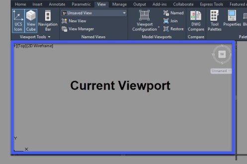
There are two types of viewports in AutoCAD. Model Space viewports and Layout space viewports. Viewports are areas that display different views of your drawing and/or model. Layout viewports are objects that you can scale to display the view of your drawing on a layout tab for publishing and production. In model space, you can split the drawing area into one or more rectangular areas called model space viewports. Viewports are areas that display different views of your model. In large or complex drawings, displaying different views reduces the time needed to zoom or pan in a single view. You can configure these viewports from the View tab on the Ribbon as shown.

The illustrations below show several model space viewport configurations. You can save and restore viewport configurations by name with the VPORTS command or pulling down the Viewport Configuration from the ribbon as shown.

When you display multiple viewports, the one that is highlighted with a blue rectangle is called the current viewport – shown as 1 below. The remaining viewports will be displayed grayed out as for not used.
from Autodesk Help – these points describe the options you have when using model space viewports.
- Commands that control the view, such as panning and zooming, apply only to the current viewport.
- Commands that create or modify an object are started in the current viewport, but the results apply to the model and can be visible in other viewports.
- You can start a command in one viewport and finish it in a different viewport.
- You can make any viewport the current one by clicking in it.
You can modify the size, shape, and number of model space viewports in a viewport configuration:
- Choose from several viewport configurations by clicking the [+] or [-] control in the top-left corner of a viewport.
- Drag the boundaries of viewports to adjust their size.
- Press CTRL while dragging viewport boundaries to display the green splitter bar and create new viewports. Alternatively, you can drag the outermost splitter controls.
- Drag a viewport boundary onto another boundary to remove a viewport.

After you create a new viewport, you might want to maximize and center the view by double-clicking the mouse wheel to perform a zoom extents.
If you want to configure the viewports a certain way for your model move the sliders around until you get the desired configuration. Under the New name: Enter the name of your viewport and it will appear in the Named Viewports section and be able to reuse throughout your drawing session.
Annotation text objects in AutoCAD are used in drawings to determine text height or the overall scale of an annotation text object. An annotative object whether it be text or a block is set to a scale in model space at a particular paper height then when the viewport scale is changed the object changes its scale based off that factor.
If the annotative property of an annotation object is enabled, the text height or scale of the annotation object adjusts based on the current drawing annotation or layout viewport scale with the result that it will remain at the same size automatically.
Annotative Objects continue to be key learning component for many AutoCAD users. For Civil 3D users all our labels and styles are annotative which means the concept becomes more of a natural workflow.
There are two commands (one system variable) that I find helpful when working with Annotative objects. The first is the system variable SELECTIONANNODISPLAY. This variable will control the “faded visibility” or multiple scales showing up when you select the text or object as shown below.
The default value is set at 1, change the system variable to 0 and your multiple annotative scales will not appear.
Many times we want to see those different object scales giving us the visual display to help determine if the location is correct at an alternate scale. If you want the text and/or leader to be pointing at the same spot in all places then you must reset the annotative object. This can be controlled by Synchronizing Multiple-scale options as shown below.
- Select your object (text shown below)
- From the menu select Annotative Object Scale
- Select Synchronize Multiple-scale Positions.
This will reset the location of all the annotative scales to align with the current scale selected.
Attendance for Autodesk University 2020 is on-demand and FREE Nov 17-20.
I will be presenting 2 classes this year of which both include over 10 exercises and a full dataset for you to gain the knowledge you need to succeed.
Register today!
CES463390-L A Complete Guide to the Sheet Set Manager
CES463392 Improving Quality with the CAD Standards Manager in AutoCAD
Until next month or virtually at Autodesk University 2020. Sam