
As much as I like the Ribbon I still find myself creating command aliases so I can access those longer commands just a little quicker. How about changing your favorite commands to 2 letters so they can be launched from the keyboard and you can still move your mouse around. I am right-handed therefore I enter keyboard aliases with my left hand and move the mouse with my right. Here is how you do that.
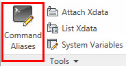
Type ALIASEDIT at the command prompt or select from the express tools tab on Ribbon as shown.
After selected AutoCAD will bring up the acad.pgp editor (shown below). Us veteran users can remember editing this file in notepad or word but since 2009 we can edit the file in a dialog box making it much easier to manage the data.

We are going to change the long MEASUREGEOM command to MG. Type in your two letter shortcut, select the command from the list, and save your settings. AutoCAD will save the file and you will now be able to use that command each and every time you load AutoCAD.

Have a Happy and Safe Memorial Day weekend!
No one likes to pick up a drawing and find out that everything has been drawn on layer 0. You could just match properties or select from the layer pull down but that may not get everything you need. Objects’ properties within blocks will not be changed. That is where the SETBYLAYER command comes in handy. The SETBYLAYER command changes property overrides for color, linetype, lineweight, material, plot style, and transparency to ByLayer for selected objects and inserted blocks on unlocked layers
Simply select from the application browser under the Home tab, modify panel (as shown below) or type SETBYLAYER at the command prompt. Select the object(s) you would like changed and hit Enter.
![]()
This command also has settings options where you can control what properties you would like changed.
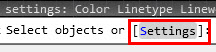
After launching the command type S (or select) at the command prompt and the following dialog box will pop up.
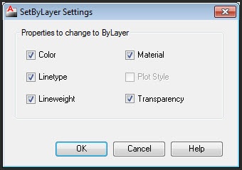
This box will control the setting of the SETBYLAYER command. Give it a try today!
Additional Layer Notes:
By creating layers, you can associate similar types of objects by assigning them to the same layer. Layers can control the following:
- Whether objects on a layer are visible or dimmed in any viewports
- Whether and how objects are plotted
- What color is assigned to all objects on a layer
- What default linetype and lineweight are assigned to all objects on a layer
- Whether objects on a layer can be modified
- Whether objects display with different layer properties in individual layout viewports
A quick tip on how to use the fillet command to close corners or trim and extend an object creating a 90 degree angle. Yes, you can simply set your fillet radius to 0 and select two lines but what if we did not want to change our radius. Let’s say we want to keep our radius set to a standard value. This is where we can use the SHIFT key to help out.
Draw crossing lines as shown below (top left of image). Type fillet then hold down your shift key and select lines 1 and 2. AutoCAD will close the corner and you will have a 90 degree angle. Another tip would be if you would like to create an arc between two parallel lines. Simply type fillet and select the lines 3 and 4 as shown below. AutoCAD will create an arc between the two lines as shown.

These are two simple tips on how to use the fillet command more efficiently while working in AutoCAD.
Viewing layers within a pdf file can be extremely useful to managers and clients who do not have access AutoCAD or a viewing program. Sometimes a client may have a specific request to view the layers of the drawing giving them the ability to manipulate the file. Drawings that use the DWG to PDF driver (from Autodesk) have the ability to turn on the layer control by following these three steps.
There are several ways to do this but the easiest would be to just type PLOT at the command prompt.
– Set your plotter to the DWG to PDF.pc3 file as shown below, then select properties.

– Highlight custom properties on the files tab and select the Custom Properties button.

– After selecting the Custom Properties button the following dialogue box will appear. By default the include layer information is checked. Simply uncheck that box and hit ok. The settings will be saved to the printer driver and you are ready to go.

That’s it! Simply open your drawing in Adobe or another PDF reader and you will notice you have full control over your layers.
With SHELL, you can execute operating system (OS) commands while remaining in AutoCAD. Type SHELL at the command prompt and AutoCAD will prompt you for an OS command. When the command has been executed, SHELL launches the program in a new window. For example you can type Explorer (to launch windows explorer) or Notepad (to launch Notepad).
Although shell commands can be helpful I found it even better to add a little lisp to the equation. Typing Explorer at the command prompt brings you to a default directory on your local drive. What I would like to do is type explorer and look at my project folder where my current drawings are located. This can be very helpful when trying to manage project data.
This handy little lisp routine (shown below) will bring up explorer to the current project directory you are in.
(defun c:expl ()
(startapp “explorer” (strcat “/n,/e,” (getvar “dwgprefix”)))
(princ)
)
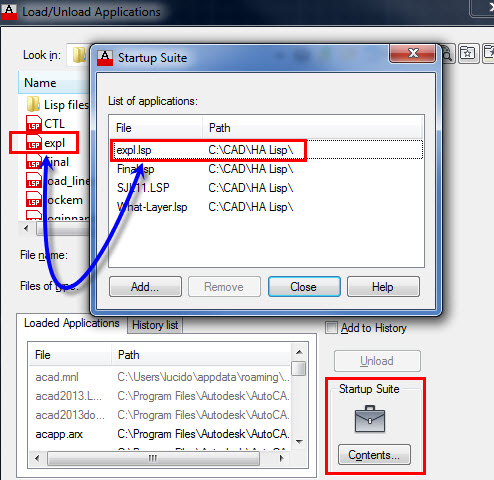
Copy or paste the code into notepad (or any text editor) and name it expl.lsp. Next type appload at the command prompt and place that lisp file in your startup suite (see image below). Of course you do not have to do that but it’s nice to have that command available at all times.
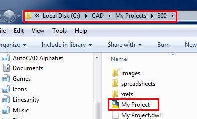
After you type expl you will be taken out to the current folder where your drawing is located. For this example I have been taken out to the folder my projects where my drawing named My Project.dwg is located.
This is a great tool for managing project files and folders. Let’s take this one step further. Have you ever wanted to go directly to the folder that contains your backup (.bak) files? Maybe after a crash or a change you need to go back. Using the same code simply change a variable to the autosave setting (savefilepath variable) as shown. We will name this one exps.lsp
(defun c:exps ()
(startapp “explorer” (strcat “/n,/e,” (getvar “savefilepath”)))
(princ)
)
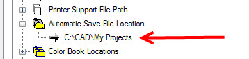
This command will take you out to the folder where you backup files are located. This folder location is stored in the options menu as shown.
You now have quick access to you project folders and you backup files. Put both in your startup suite and you will be much more efficient when working with project folders and backup files.
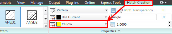
Did you know that you can add color to the background of a hatch pattern? This can help when two areas are similar but have one small difference that you need to graphically display. Select Hatch from the Home tab on the Ribbon as shown.

The contextual hatch pattern ribbon will appear. Select your background color as shown below. Change your background color.
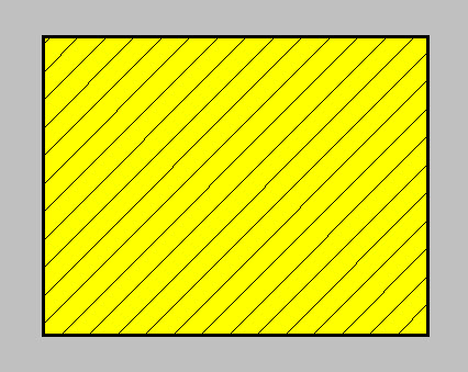
Now you have one hatch pattern with a background color! You might want to change the transparency while you are there. To the right of the background fill notice the hatch transparency slider bar. Simply slide that to the right for a lighter fill and back to the left for the original solid color.
If you already have an existing hatch in your drawing bring up the properies pane (CTRL+1) or right click the hatch and you can perform the same functions as if you were just creating the pattern.

Do you still draw lines and place text within those areas to look like a table? I bet it’s safe to say that all those tables or charts are not consistent. A table is an object that contains data in rows and columns. A table object can be created from an empty table or table style. A table can also be linked to data in a Microsoft Excel spreadsheet.
Similar to dimensions you can create your table first setting all the parameters using the properties pane (CTRL+1) or the table contextual ribbon. Type Table at the command prompt and create a table which has all of your company standards (line weights, fonts, shading, etc.).
Then select your table as if you were to move the entire table.
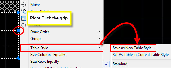
Simply right-click, select Table Style, and Save as New Table Style.
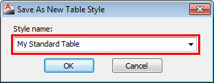
You can now use designcenter, insert, or simply create a template where you can begin your tables with this style every time.
The WordPress.com stats helper monkeys prepared a 2012 annual report for this blog.

Here’s an excerpt:
The new Boeing 787 Dreamliner can carry about 250 passengers. This blog was viewed about 1,100 times in 2012. If it were a Dreamliner, it would take about 4 trips to carry that many people.
If you spend a lot of time using several commands on a particular panel in the Ribbon you can simply pull out your favorite panel and place in the drawing area or on another monitor (if you have two). Simply right-click on the panel you would like to move and drag out to the drawing area (make sure you do not click on a command). For this example we will pull out the layer panel.

You can move the panel around by selecting the side tabs (dark sides shown below). When you want it back on the ribbon select the arrow as shown and the panel will be placed back on the ribbon where it was originally located. Even if you are on another tab!

Browse a website from inside AutoCAD. The browser command will allow you to type a web address at the command line and load your current browser. Simply type BROWSE at the command line and type in the website or hit return for the default setting (www.autodesk.com). You can change the default location of your browser with the system variable “INETLOCATION” Once that is set, when you launch the browser command the location you specified will show as default, or you can enter whatever you want.
How about placing a command to your company website on a tool palette as shown below? A quick tip before we make the trip to Las Vegas Have a safe trip and I look forward to meeting you all next week.
